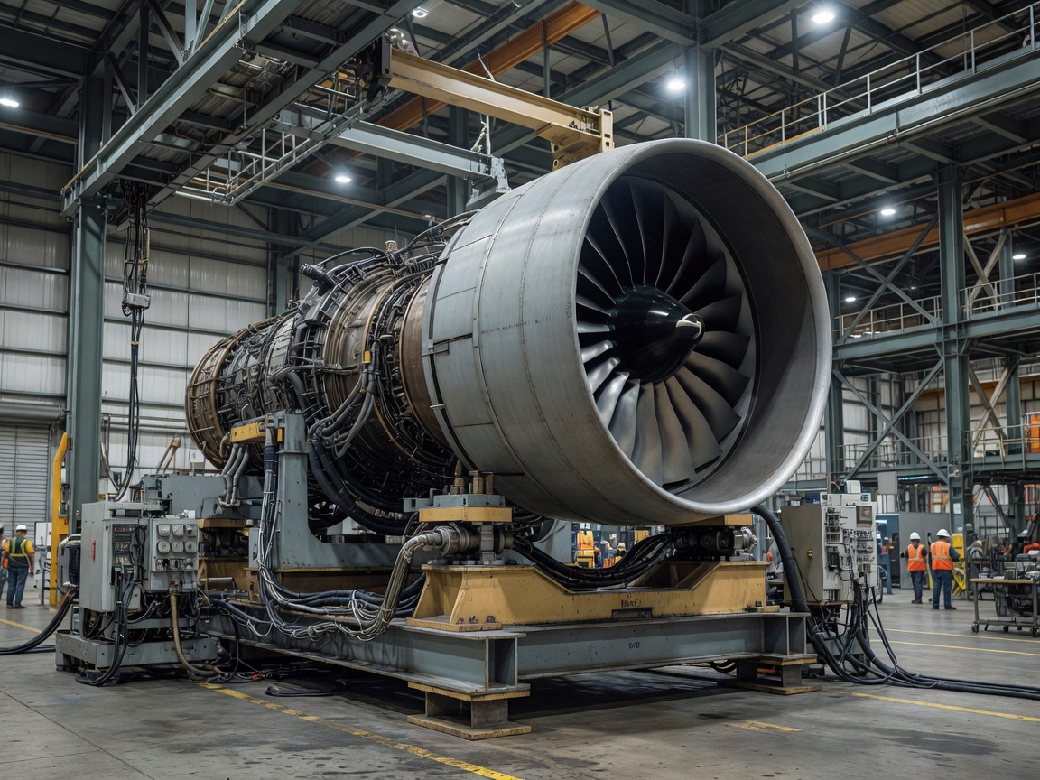
1. Physical Architecture and Fan Diameter
The General Electric GE9X-105B1A is designed exclusively to power the Boeing 777X family. With a fan diameter of 134 inches (3.40 meters), the front nacelle of the GE9X is wider than the fuselage barrel of a Boeing 737 airliner (148 inches vs. 140 inches external nacelle cowl width). Despite this monumental scale, the GE9X achieves high structural efficiency by reducing the blade count to just 16 fourth-generation carbon-fiber composite fan blades. For comparison, the predecessor GE90-115B utilized 22 fan blades, and the original GE90-76B featured 24 blades.
The blades feature a three-dimensional aerodynamic sweep along with steel trailing-edge and titanium leading-edge caps to defend against foreign object debris (FOD) and bird-strike events. The reduced blade count reduces rotational mass while broadening the throat area between blades, maximizing low-pressure airflow through the bypass duct.
2. Thermodynamic Cycle and Pressure Ratio
The core engine architecture represents an evolutionary leap in commercial Brayton-cycle thermodynamic performance. The 11-stage high-pressure compressor (HPC) achieves a pressure ratio of 27:1—the highest pressure ratio of any commercial production engine in service. Combined with the low-pressure spool stages, the overall pressure ratio (OPR) of the GE9X exceeds 60:1 during cruise climb settings.
Thermodynamic Specification Profile
Bypass Ratio: 10:1 (nominal bypass air to core mass flow)
Compressor Pressure Ratio: 27:1 across 11 stages
Overall Pressure Ratio (OPR): ~60:1 at top-of-climb
Certified Takeoff Thrust: 105,000 lbf (470 kN) nominal; tested beyond 134,000 lbf in boundary trials
3. Ceramic Matrix Composites (CMCs) in the Hot Section
Operating at an extreme overall pressure ratio produces turbine inlet temperatures that exceed the melting point of conventional single-crystal nickel superalloys. Rather than diverting excessive amounts of cooling bleed air from the compressor—which erodes thermal efficiency—GE Aerospace integrated Ceramic Matrix Composites (CMCs) into the combustor and high-pressure turbine (HPT).
CMCs are composed of silicon carbide (SiC) matrix and fibers. They deliver one-third the density of nickel alloys while withstanding continuous operational temperatures up to 2,400°F (1,315°C). In the GE9X, CMCs are utilized across:
- The inner and outer combustor liners, mitigating thermal cracking under lean-burn conditions.
- Stage 1 and Stage 2 high-pressure turbine nozzles, directing combustor gases into the rotor blades.
- Stage 2 high-pressure turbine shrouds, reducing clearance expansion gaps over the blade tips.
By drastically reducing core cooling flow requirements, more high-pressure air participates directly in power extraction, contributing significantly to the engine’s 10% lower specific fuel consumption (SFC) compared to the GE90-115B.
4. Twin-Annular Premixing Swirler (TAPS III) Combustor
Stringent ICAO Committee on Aviation Environmental Protection (CAEP) standards mandate severe limits on nitrogen oxide (NOx) emissions during low-altitude airport operations. The GE9X employs the third-generation Twin-Annular Premixing Swirler (TAPS III) combustor system. TAPS III premixes jet fuel and compressor discharge air prior to entry into the combustion chamber, maintaining a lean fuel-to-air mixture that eliminates localized hot spots where NOx thermal formation peaks. Consequently, the GE9X comfortably complies with CAEP/8 standards with substantial margin.